Stairs trip up more floor plans than any other element. Drawn wrong they read as a random ladder of lines; drawn right they tell a builder the run, the direction of travel, the number of risers and where the flight is cut between storeys. This guide covers the standard conventions for showing stairs on a floor plan, the main stair types and their symbols, the UK Building Regulations numbers worth checking before you commit a stair to a drawing, and how RoomPlot draws each type with real geometry so your plan reads like a professional drawing.
How stairs are drawn on a plan
A staircase on a plan is a top-down view taken at a notional cutting plane roughly 1.2 m above the floor, so every step shows as a line - the tread nosings - inside the run. Four conventions make it readable:
- Treads as parallel lines across the width of the flight, evenly spaced to match the actual going of the steps.
- A direction arrow along the centre line, starting at the lowest riser on that storey and labelled UP or DN to say which way the flight travels from that floor. Many drawings add the riser count next to it, e.g. UP 13R.
- A break line - a heavy diagonal or zig-zag - where the flight passes through the cutting plane. It marks a break in the view, not a break in the stair, and lets the plan show whatever sits under the upper steps.
- Dashed lines for anything above the cut - the treads beyond the break line, or a bulkhead over the flight, are drawn dashed because they are overhead rather than at floor level.
Get those right and the stair is unambiguous. The same flight appears on two storeys: marked UP on the lower floor and DN on the floor it climbs to, in exactly the same position on both sheets.
The main stair types
Not every stair is a simple straight flight. The common shapes you will draw are a straight run, a quarter-landing (a flight that turns 90 degrees at a landing), a winder (which turns using tapered treads instead of a landing) and a spiral. Each has its own footprint and its own symbol:
The stair dimensions worth checking
If your plan supports a conversion, extension or building-control submission, the stair has to work in three dimensions, not just look right in two. For a private stair in a dwelling in England, Approved Document K of the Building Regulations sets the figures most surveyors sanity-check on plan:
- Rise: maximum 220 mm per step, and every rise in a flight must be equal.
- Going: minimum 220 mm (the horizontal depth of each tread on plan - this is what your tread-line spacing represents).
- Pitch: maximum 42 degrees; twice the rise plus the going should fall between 550 mm and 700 mm for a comfortable step.
- Headroom: 2.0 m measured vertically from the pitch line, relaxed for loft conversions to 1.9 m at the centre of the flight and 1.8 m at the edge.
- Landings: a clear landing at the top and bottom of every flight, at least as long and as wide as the narrowest width of the flight, and kept free of door swings.
- Handrails: on at least one side; on both sides where the flight is 1000 mm or wider.
A quick worked example: a typical 2.6 m floor-to-floor height at a 200 mm rise gives 13 risers, and at a 220 mm going the flight needs roughly 2.64 m of horizontal run plus landings. If that does not fit the space on your plan, you know before anyone builds anything. Requirements differ in Scotland, Wales and Northern Ireland, and existing buildings are judged case by case - confirm the specifics with your local building control body or a competent designer before relying on them.
Tip. Always add the UP or DN arrow, even on a short flight, and note the riser count beside it. Those two marks tell a reader which way the stair goes and how far it climbs without cross-referencing another sheet - and they are exactly what a building-control officer looks for first.
Draw them in RoomPlot
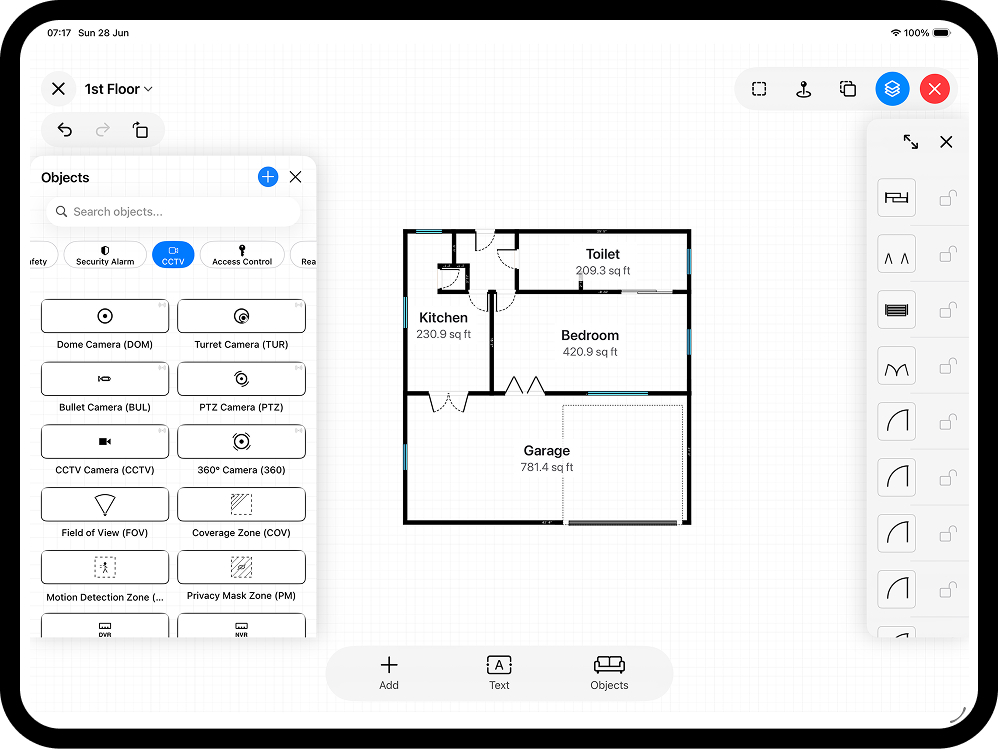
Open the object library and switch to the Stairs category. RoomPlot ships four stair types - Straight, Quarter Landing, Double Winder and Spiral - and each is drawn as true vector geometry for its type, so the treads and the turn are correct rather than a generic box. The workflow on site:
- Measure the opening - the length and width of the stairwell, not the stair itself. On a LiDAR-equipped Pro device you can capture the room with an AR scan and place the stair into the scanned footprint; otherwise draw the walls manually with smart snapping.
- Place the stair symbol and resize it to the measured run and width, in metric or imperial. Rotate it so the first riser sits where the flight actually starts.
- Label the direction with a Stairs Up or Stairs Down marker from the Real Estate symbol set.
- Flag constraints - if the flight runs under a slope, add a Reduced Headroom symbol so the plan shows where the ceiling closes in, and attach a photo or voice memo to the stair as evidence for the report.
Stairs across floors
Stairs are the one element that ties storeys together, so they need to line up between floors. In RoomPlot, add a floor for each storey in the same multi-floor project and place the flight in the same position on each, marked UP on the lower floor and DN on the upper. It is the quickest check that the stairwell is continuous, that the trimmed opening in the upper floor matches the flight below, and that nothing under the stair clashes with the landing above.
Export the plan
When the stairs read cleanly, export a PNG or single-page PDF for a quick send, a DXF if the plan is going on to CAD, or a branded multi-page PDF report with an automatic symbol legend that lists every symbol used - stairs included. Want the wider vocabulary of plan symbols? See our guide to floor plan symbols, or browse the full set of RoomPlot guides. Open RoomPlot, drop in a stair, add the direction arrow and riser count, and your plan will read the way a professional drawing should.