
A zone plan is the first thing a responding firefighter looks at when the panel goes into alarm. It turns a flashing zone number into a place on a map - "Zone 3, first floor, east stairwell" - in the seconds that matter. And under BS 5839-1:2025, the current UK fire-detection standard, it is no longer optional: omitting a zone plan is classed as an unacceptable variation, and an outdated or inaccurate one is a major non-conformity. This guide walks fire-alarm installers through building a clear, multi-floor zone plan on an iPhone: laying out the building, dropping fire symbols, colouring the zones, adding a title block and company branding, and showing detector coverage on the plan itself.
What BS 5839-1:2025 expects from a zone plan
BS 5839-1:2025 requires a zone plan to be displayed adjacent to every fire alarm control and indicating equipment (CIE) - the panel - and treats its omission as an unacceptable variation (Clause 6.6), particularly in multi-storey buildings and anywhere people sleep. The absence of a plan, or the presence of one that no longer matches the building, is classed as a major non-conformity on inspection. The reasoning is grim and practical: at the Rosepark Care Home fire in 2004, an accurate, correctly orientated zone plan could have helped crews find the fire faster.
The standard also says what the drawing must do. A compliant zone plan is a geographical representation of the building that clearly shows:
- The division of the building into fire alarm zones, unambiguously.
- Final exits, common escape routes, circulation areas, and stairs.
- Correct orientation to the reader's position, with a "You Are Here" marker so a responder standing at the panel can match the plan to the building instantly.
Behind the drawing sit the zone-design rules the system designer works to: a detection zone should not exceed 2,000 m² of floor area, and the search distance to locate a fire within a zone should not exceed 60 m from the point of entry. Zones normally do not span storeys.
This guide is about producing that drawing cleanly and quickly. It is not compliance advice: the number and boundaries of detection zones, the siting of the plan, and the symbols your authority expects are decisions for the system designer, a competent person, and the current edition of the standard. RoomPlot gives you the tools to draw it well - what goes in each zone is your call.
Step 1 - Build the building shell
Start with accurate geometry. If you are working in an occupied building with a recent iPhone or iPad Pro, scan each area: walk the perimeter and RoomPlot uses LiDAR to detect walls, doors, and windows automatically. Working from a drawing, or on a non-LiDAR device? Draw the walls by hand - snapping keeps corners square and walls aligned, so a freehand outline still comes out clean. Either way, the scan or sketch becomes a fully editable plan: move a wall, set an exact length, add an opening.
Because a zone plan almost always spans more than one storey, build each floor as its own floor in the same project. You can switch between floors, keep them aligned, and - where it helps the responder - combine the floors into a single 2D view so a stairwell or riser reads continuously top to bottom. Make sure the stairs, corridors, and final exits the standard asks for are all recognisable on the shell before you move on.
Keep the shell simple. A zone plan is not a survey drawing. Capture enough wall detail to make rooms, stairs, and exits recognisable, then stop - every extra line you leave in competes with the zone colours and symbols for a reader's attention.
Step 2 - Colour-code the zones
Zones are the whole point, so make them unmistakable. RoomPlot detects enclosed rooms automatically and lets you give each area its own name, colour, and label, so you can wash every space in a zone with one colour and drop a styled zone label on top. Keep a single colour per zone across every floor - if Zone 2 is amber on the ground floor, it should be amber on the first floor too - and the plan becomes readable at a glance.
- Fill each area with its zone colour and place a clear zone label (Zone 1, Zone 2, …) matching the zone numbering on the panel exactly.
- Re-use the same colour for the same zone on every floor for instant cross-floor recognition.
- Add a "You Are Here" marker - BS 5839-1:2025 expects the plan to be correctly orientated from where it is mounted, and the marker is how you prove it.
- Use a colour key in the corner so the colours are self-explanatory.
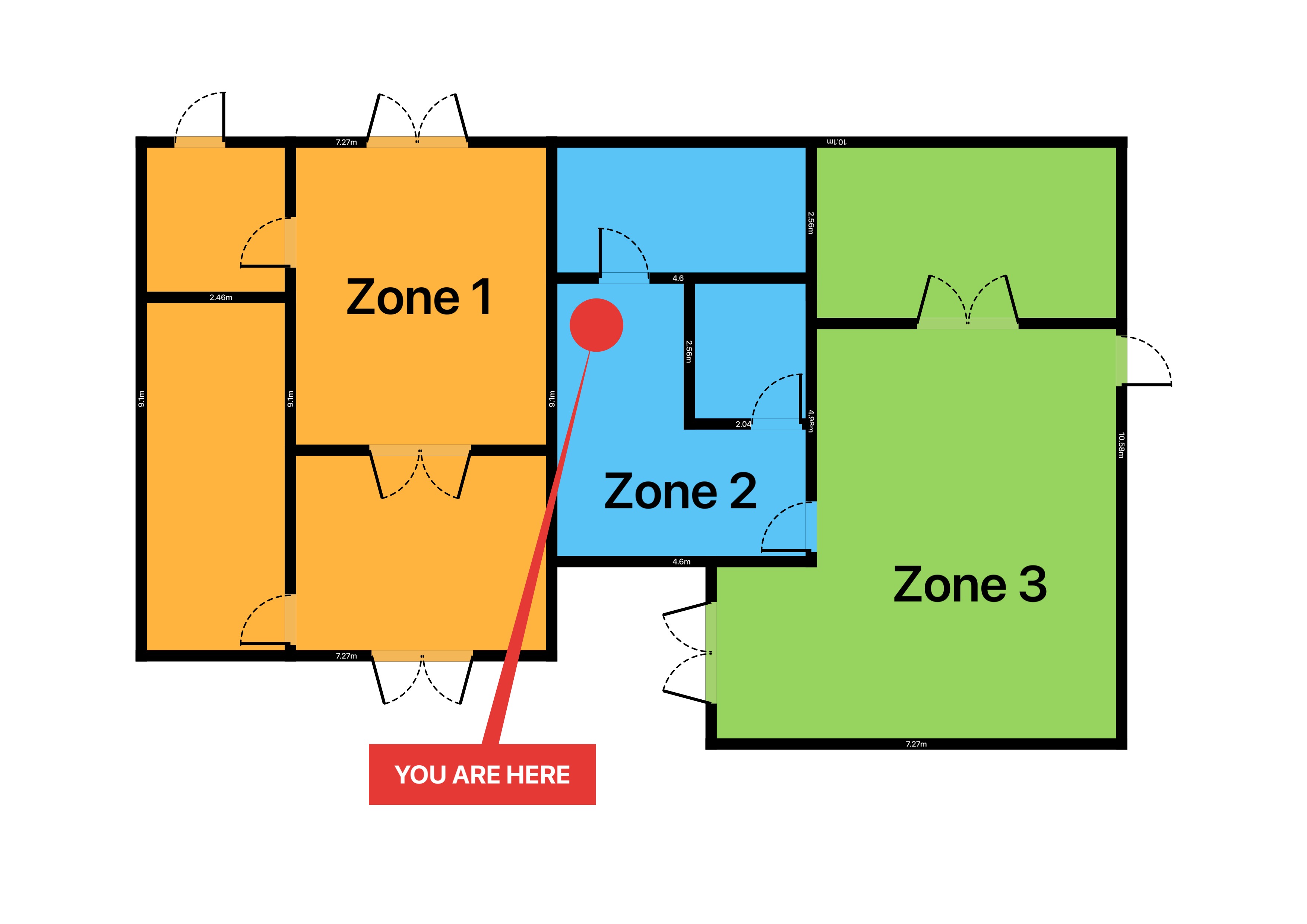
Step 3 - Place fire symbols from the library
RoomPlot ships a dedicated fire-alarm symbol library alongside its general vector and furniture libraries, so you mark up the plan with the devices the system actually uses rather than improvising shapes. Drop a symbol, slide it into place, and rotate or resize it so the layout matches what was installed.
- Detection - smoke detectors, heat detectors, and other point devices.
- Manual call points and sounders where you need to record them on the plan. (For reference, BS 5839-1:2025 tightened call-point siting to a maximum of 45 m along the actual walking route to the nearest call point - worth checking as you plot them.)
- The control panel and any repeater positions, so the plan ties back to the indicator.
If your authority or your house style expects a glyph that is not in the stock set, the custom-symbol editor lets you build your own vector symbol once and re-use it across projects. Custom symbols sync with the rest of your work, so a glyph you draw on the iPhone is there when you continue on the iPad.
Step 4 - Show detector coverage on the plan
This is where RoomPlot does something most drawing tools cannot. Drop a smoke or heat detector and the app draws the area it covers directly on the plan - a detection-radius circle sized to the device. The nominal radii follow the figures installers already know: roughly 7.5 m for a smoke detector and 5.3 m for a heat detector under BS 5839-1 / NFPA 72. Coverage is enabled automatically when you place the device, and fire devices render in red so they read as a family.
Coverage circles are a fast visual sanity check while you lay out a plan - overlap them across a room and you can see at a glance where a zone is densely covered and where a corner sits outside every circle. You can hide or disable coverage for a clean print, and the same coverage information can be carried into a coverage report.
Coverage circles are a drawing aid, not a design certificate. The radii are nominal values for visualisation. Ceiling height, beams and ductwork (BS 5839-1:2025 added specific rules for obstructions up to 250 mm deep), and the device datasheet all affect real spacing - treat the circles as a way to see your layout, and let the system designer and the standard set the actual positions.
Step 5 - Add the title block and company branding
A zone plan is a controlled document, and it should look like one. Give the plan a clear title - building name, floor, and "Fire Alarm Zone Plan" - and stamp on your company branding: logo, address, and client details. A North marker, set once, keeps every floor and every export oriented the same way, which matters when a responder is matching the plan to the building. Use the layers panel to lock the shell and the title block so a stray drag during a later service visit cannot nudge them out of place.
| Plan element | Why it earns its place |
|---|---|
| Title + floor name | Tells the reader exactly which sheet and storey they are looking at. |
| Company logo & details | Identifies who maintains the system and who to call. |
| Colour key / legend | Makes the zone colours and symbols self-explanatory. |
| North marker | Orients the plan to the building, the same way on every floor. |
| "You are here" marker | Anchors the reader at the mounting point by the panel - and satisfies the standard's orientation requirement. |
| Revision date | An out-of-date plan is a major non-conformity; a visible date makes staleness obvious at service visits. |
Step 6 - Export and mount
When the plan is finished, RoomPlot produces the deliverables a fire-alarm job needs from the same project:
- Branded PDF - a print-ready zone plan, or a full multi-page report with legends, client and company details, and your branding, ready to frame at the panel.
- DXF - editable CAD geometry to hand to a consultant or feed into a wider drawing set.
- Image (PNG/JPG) - a crisp A4 or 300 dpi plan image for an O&M manual, an email, or a job sheet.
Because each floor lives in the same project, you can export the set as a consistent pack - same colours, same symbols, same orientation across every storey - rather than chasing a matching look across separate files. Mount the printed plan adjacent to the CIE, orientated to match the reader's view, and leave a copy in the site logbook.
A practical workflow
- Scan or draw each floor; keep the shell clean and make sure stairs, escape routes, and final exits read clearly.
- Detect rooms, then fill and label each zone with a consistent colour across floors, matching the panel's zone numbering.
- Drop fire symbols - detectors, call points, sounders, the panel - and tidy their positions.
- Use detection-radius circles to eyeball coverage, then hide them for the final print.
- Add the title, branding, colour key, revision date, North marker, and "you are here"; lock the layers.
- Export a branded PDF for the panel and a DXF or image for the document set.
Common mistakes to avoid
- Inconsistent zone colours. If a zone changes colour between floors, the plan stops being readable at a glance - pick a colour per zone and hold it.
- A plan that no longer matches the building. Under BS 5839-1:2025 an inaccurate or outdated zone plan is a major non-conformity. Update the drawing whenever zones, walls, or exits change - with the project on your phone, a revision is minutes, not a re-draw.
- Wrong orientation. The standard expects the plan correctly orientated to the reader. Without a North marker and a "you are here", a responder has to guess which way they are facing.
- An over-detailed shell. Survey-grade clutter fights the zones for attention. Keep walls recognisable and let colour do the work.
- Leaving coverage circles on the final print. They are a layout aid - turn them off before you export the mounted copy unless the reader needs them.
Frequently asked questions
Is a zone plan actually mandatory?
Under BS 5839-1:2025, omitting a zone plan is listed as an unacceptable variation, and inspection bodies treat a missing, outdated, or inaccurate plan as a major non-conformity. The responsible person and system designer should confirm requirements for the specific building with a competent person - but in practice, plan for every panel to have one.
Can I build a fire-alarm zone plan across several floors in one project?
Yes. Add each storey as its own floor, switch between them, and combine floors into a single 2D view where it helps a stairwell or riser read continuously. Zones themselves normally do not span storeys.
How big can a detection zone be?
As a design rule under BS 5839-1, a single zone should not exceed 2,000 m² of floor area, and the search distance to locate a fire within the zone should not exceed 60 m. Zone boundaries are the system designer's call - the plan's job is to show them clearly.
Does RoomPlot draw detector coverage?
It does. Place a smoke or heat detector and the app draws a detection-radius circle on the plan - roughly 7.5 m for smoke and 5.3 m for heat as nominal BS 5839-1 / NFPA 72 radii. You can hide it for a clean print.
What if a symbol I need isn't in the library?
Use the custom-symbol editor to draw your own vector symbol once. It re-uses across projects and syncs to your other devices.
Which format should I mount at the panel?
A branded PDF - print-ready and consistent across floors. Send a DXF to a consultant who works in CAD, and use an image export for manuals or email.
Building your first zone plan on a job this week? Start by capturing the building shell - see how to create a floor plan and how to measure a room for the basics, or browse more guides. Then drop your zones, symbols, and coverage, and export a plan that earns its place beside the panel.